
In high-hazard industries such as oil and gas, chemicals, power generation, and pharmaceuticals, a single failure of a protective system can lead to catastrophic consequences — fires, explosions, toxic releases, injuries, and fatalities. To manage these risks in a structured, measurable way, the concept of Safety Integrity Level (SIL) was developed. SIL provides a common language for engineers, operators, and regulators to define how reliable a safety system must be, and to prove that it actually delivers that reliability in practice.
This guide explains what Safety Integrity Level means, how the four SIL ratings differ, which standards govern SIL, how target levels are assigned and verified, and what organisations must do to maintain SIL compliance across the entire safety lifecycle.
What Is a Safety Integrity Level (SIL)?
A Safety Integrity Level is a discrete measure of the risk reduction provided by a Safety Instrumented Function (SIF). In simpler terms, it tells you how dependable an automated safety function needs to be in order to bring a hazardous process down to a tolerable level of risk.
A crucial point that is often misunderstood: SIL does not apply to an entire plant, a single device, or even a complete Safety Instrumented System (SIS). It applies to an individual safety function — for example, "close the inlet valve when pressure in the separator exceeds the high-high setpoint." Each safety function in a facility may have a different SIL requirement depending on the severity and likelihood of the hazard it protects against.
SIL as a Measure of Probability of Failure
SIL is expressed through the Probability of Failure on Demand (PFD) for low-demand systems, or through the Probability of Failure per Hour (PFH) for high-demand or continuous systems. A low-demand system is one that is called upon to act infrequently — typically less than once per year — such as an emergency shutdown function. A high-demand or continuous system operates frequently or constantly, such as a machinery control safety function.
The higher the SIL, the lower the acceptable probability of failure, and the greater the risk reduction the function must deliver.
The Relationship Between SIL and Risk Reduction
Every SIL corresponds to a Risk Reduction Factor (RRF), which is simply the inverse of the average PFD. A function with a PFD of 0.01 has an RRF of 100, meaning it reduces the underlying risk by a factor of one hundred. Understanding this relationship is essential because SIL determination always starts with a question: how much risk reduction do we need to move from the unmitigated risk to a tolerable risk?
The Four SIL Levels and What They Mean
The international standards define four Safety Integrity Levels, ranging from SIL 1 (lowest integrity) to SIL 4 (highest integrity).
SIL 1 – Basic Risk Reduction
SIL 1 requires an average PFD between 0.1 and 0.01, corresponding to a risk reduction factor of 10 to 100. SIL 1 functions are typically applied where the consequences of failure are limited — perhaps minor injury or modest asset damage. Many alarm-and-trip functions in process plants fall into this category. While SIL 1 is the least demanding level, it still requires formal design, documentation, verification, and periodic proof testing.
SIL 2 – Intermediate Risk Reduction
SIL 2 requires a PFD between 0.01 and 0.001, equivalent to a risk reduction factor of 100 to 1,000. This is the most common target level in the process industries. SIL 2 functions usually protect against scenarios that could cause serious injury, a single fatality, or significant environmental or financial damage. Achieving SIL 2 often requires higher-quality field devices, more rigorous proof-testing regimes, and sometimes redundant architectures.
SIL 3 – High Risk Reduction
SIL 3 requires a PFD between 0.001 and 0.0001, or a risk reduction factor of 1,000 to 10,000. SIL 3 functions guard against major accidents involving multiple fatalities or severe off-site consequences. Designing to SIL 3 almost always demands hardware fault tolerance (redundant sensors, logic solvers, and final elements), certified components, strict management of systematic failures, and frequent, well-executed proof tests. SIL 3 is generally considered the practical upper limit for process industry applications.
SIL 4 – The Highest Integrity Level
SIL 4 requires a PFD between 0.0001 and 0.00001, providing a risk reduction factor of 10,000 to 100,000. SIL 4 is extremely rare in the process sector. If a risk assessment indicates that SIL 4 is needed, most practitioners treat that as a signal that the process design itself is unsafe and should be changed — through inherently safer design, additional independent protection layers, or process modification — rather than relying on a single instrumented function of extraordinary integrity. SIL 4 is more commonly associated with sectors such as rail signalling and nuclear applications, governed by their own derivative standards.
The Standards Behind SIL – IEC 61508 and IEC 61511
Safety Integrity Levels are defined and governed by a family of international functional safety standards.
IEC 61508 – The Umbrella Standard
IEC 61508, "Functional Safety of Electrical/Electronic/Programmable Electronic Safety-Related Systems," is the foundational standard. It is sector-agnostic and primarily aimed at equipment manufacturers and developers of safety-related systems. IEC 61508 defines the four SIL levels, sets requirements for hardware reliability, hardware fault tolerance, safe failure fraction, and systematic capability, and establishes the overall safety lifecycle model. When a vendor claims a transmitter or valve is "SIL certified," that certification is normally issued against IEC 61508.
IEC 61511 – The Process Industry Standard
IEC 61511, "Functional Safety – Safety Instrumented Systems for the Process Industry Sector," adapts the principles of IEC 61508 specifically for end users and engineering contractors in the process industries. It covers hazard and risk assessment, allocation of safety functions, SIS design and engineering, installation, commissioning, validation, operation, maintenance, modification, and decommissioning. In the United States, ANSI/ISA 61511 (formerly ISA S84) is the equivalent standard, and OSHA recognizes it as good engineering practice under the Process Safety Management regulation.
Related Sector Standards
Other industries have their own adaptations: IEC 62061 and ISO 13849 for machinery safety (the latter using Performance Levels rather than SILs), EN 50126/50128/50129 for railways, and ISO 26262 for automotive applications, which uses Automotive Safety Integrity Levels (ASILs). While the terminology varies, the underlying philosophy — quantified, lifecycle-managed risk reduction — is consistent.
How SIL Targets Are Determined
Assigning a SIL target is a risk assessment activity, not a design activity. It answers the question: how much risk reduction must this safety function provide?
Process Hazard Analysis as the Starting Point
SIL determination begins with a structured hazard identification study, most commonly a HAZOP (Hazard and Operability Study). The HAZOP identifies hazardous scenarios, their causes, their consequences, and the safeguards already in place. Scenarios that rely on instrumented protection are then carried forward into SIL determination.
Layer of Protection Analysis (LOPA)
LOPA is the most widely used semi-quantitative method for SIL determination. For each hazardous scenario, the analyst estimates the initiating event frequency, applies credits for Independent Protection Layers (IPLs) such as relief valves, dikes, alarms with operator response, and basic process control functions, and compares the resulting mitigated frequency against the organisation's tolerable risk criteria. The remaining gap — the additional risk reduction still needed — defines the required SIL of the safety instrumented function. If the gap demands a risk reduction factor of 250, for example, the function must be designed to SIL 2 with a specific RRF target of at least 250.
Risk Graphs and Risk Matrices
Qualitative and semi-qualitative methods such as calibrated risk graphs and hazard matrices are also permitted by the standards. A risk graph walks the analyst through parameters such as consequence severity, occupancy (how often people are exposed), the probability of avoiding the hazard, and demand rate, leading to a SIL target. These methods are faster than LOPA but tend to be more conservative and less precise, which is why many operators use them for screening and reserve LOPA for the more significant scenarios.
How SIL Is Verified and Achieved
Once a target SIL has been assigned, the design team must demonstrate that the proposed safety function actually meets it. Verification rests on three pillars.
PFD Calculation
The average probability of failure on demand for the complete loop — sensor, logic solver, and final element — is calculated using failure rate data, voting architecture, proof test intervals, proof test coverage, diagnostic coverage, and mission time. Importantly, the final element (typically a valve and its actuator) usually dominates the PFD, often contributing well over half of the total. A common error is to focus certification attention on transmitters and logic solvers while neglecting valve performance and partial stroke testing.
Architectural Constraints and Hardware Fault Tolerance
Meeting the PFD target alone is not sufficient. The standards impose minimum Hardware Fault Tolerance (HFT) requirements depending on the SIL and the quality of the reliability data. HFT describes how many dangerous failures a subsystem can tolerate and still perform its function — a 1oo2 (one out of two) voting arrangement has an HFT of 1. These architectural constraints exist because failure rate calculations carry uncertainty, and redundancy provides protection against that uncertainty.
Systematic Capability and Management of Functional Safety
Random hardware failures can be calculated; systematic failures — design errors, software bugs, specification mistakes, installation errors, human error in maintenance — cannot. The standards address them through quality processes: competency management, independent verification, configuration management, and rigorous documentation. A device must hold a systematic capability rating at or above the target SIL, and the organisation operating the SIS must follow a Functional Safety Management (FSM) system to keep systematic failures under control.
The Safety Lifecycle – SIL Is Not a One-Time Exercise
Perhaps the most important principle in modern functional safety is that SIL compliance must be maintained throughout the life of the facility.
Operations, Maintenance and Proof Testing
Every PFD calculation assumes a proof test interval and a proof test coverage. If a valve was assumed to be tested every twelve months and the site stretches that to thirty months because of turnaround scheduling, the function may silently drop below its required SIL. Proof test procedures must detect the dangerous undetected failures assumed in the calculation, results must be recorded, and failures must be analysed and fed back into the reliability assumptions.
Management of Change and Periodic Revalidation
Process changes, equipment substitutions, setpoint adjustments, and bypass practices can all invalidate the original SIL assessment. A disciplined Management of Change process must trigger re-evaluation of affected safety functions. Most operators also conduct periodic SIS revalidation — typically every five years or in line with PHA revalidation cycles — comparing actual demand rates and failure history against the assumptions made during design.
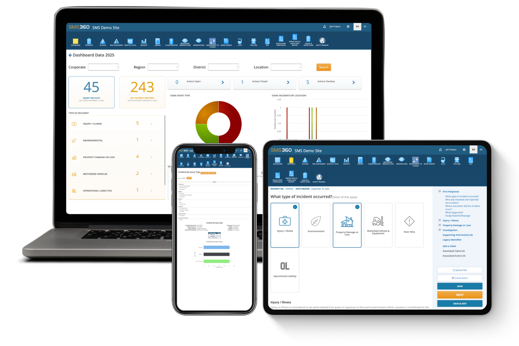
The Role of Digital Safety Management Systems
Managing hundreds of safety functions, their proof test schedules, bypass logs, demand records, and failure data is practically impossible with spreadsheets alone. Modern safety management software platforms centralise SIF registers, automate proof test scheduling, track overrides and impairments, and provide auditable evidence of ongoing SIL compliance — turning functional safety from a periodic project into a continuously managed process.
Common Misconceptions About SIL
Several persistent myths cause real problems in industry. First, "SIL-certified device" does not mean "SIL-compliant function" — a SIL 3 capable transmitter installed in a poorly designed loop with an untested valve delivers nothing close to SIL 3. Second, higher SIL is not automatically better; over-specifying SIL inflates capital and lifecycle costs, increases spurious trip rates, and adds maintenance burden without proportional safety benefit. Third, SIL is not a marketing grade for plants or products — statements like "our facility is SIL 3" are technically meaningless. Finally, achieving SIL at handover means little if operations and maintenance practices do not preserve it.
Frequently Asked Questions About Safety Integrity Level
What is the difference between SIL and SIS?
A Safety Instrumented System (SIS) is the physical system — the combination of sensors, logic solvers, and final elements engineered to take a process to a safe state when predetermined conditions are violated. A Safety Integrity Level, on the other hand, is a performance requirement applied to each individual Safety Instrumented Function that the SIS performs. A single SIS may execute dozens of safety functions, and each function can carry a different SIL depending on the hazard it addresses. For example, the same logic solver might execute a SIL 1 high-level trip on a storage tank and a SIL 3 high-pressure shutdown on a gas compression train. Confusing the two leads to errors such as assigning one blanket SIL to an entire system, which either over-engineers low-risk functions or, far more dangerously, under-engineers high-risk ones. The correct approach is always function-by-function: identify each hazardous scenario, determine the required risk reduction for that scenario, and assign the SIL to the specific function that mitigates it.
How is the required SIL for a safety function actually calculated?
The required SIL emerges from a structured risk assessment rather than a single formula. The process typically starts with a HAZOP that identifies hazardous scenarios. For each scenario requiring instrumented protection, a method such as Layer of Protection Analysis is applied. The analyst establishes the frequency of the initiating event (for instance, a control loop failure occurring once every ten years), multiplies it by enabling conditions and conditional modifiers (such as probability of ignition or probability of personnel presence), and then applies risk reduction credits for each qualifying independent protection layer already in place — relief devices, physical containment, independent alarms with adequate operator response time, and so on.
The resulting mitigated event frequency is compared with the company's tolerable risk target for that consequence severity, which might be, for example, no more than one in a million per year for a single-fatality scenario. If a gap remains between the mitigated frequency and the tolerable frequency, that gap defines the risk reduction factor the new safety function must provide, and the RRF maps directly to a SIL band. An RRF of 50 lands in SIL 1, 500 in SIL 2, 5,000 in SIL 3. This is why two identical-looking functions on similar equipment can carry different SILs — the surrounding layers of protection and consequence severities differ.
What does it take to achieve and demonstrate SIL 2 or SIL 3 in practice?
Demonstrating a given SIL requires satisfying three independent sets of requirements simultaneously. First, the quantitative requirement: the calculated average PFD of the entire loop — from process connection of the sensor to the seat of the final valve — must fall within the SIL band, using justified failure rates, realistic proof test intervals, and honest proof test coverage assumptions.
Second, the architectural requirement: the standards mandate minimum hardware fault tolerance for each subsystem depending on the SIL claimed, which in practice often means redundant sensors in 1oo2 or 2oo3 voting and, for SIL 3, frequently redundant final elements as well.
Third, the systematic requirement: every device must have systematic capability suitable for the target SIL (demonstrated through IEC 61508 certification or "prior use" justification based on documented operating experience), and the organisation must operate under a functional safety management system with competent personnel, independent verification activities, and controlled documentation. In practical terms, moving from SIL 2 to SIL 3 is a substantial step: it typically doubles or triples hardware cost, demands more sophisticated diagnostics such as partial stroke testing on shutdown valves, shortens proof test intervals, and significantly increases the documentation and assessment burden. This is why good engineering practice tries to resolve high-risk scenarios through inherently safer design before resorting to SIL 3 functions.
How often must SIL-rated systems be proof tested, and what happens if testing is missed?
There is no universal mandatory interval — the proof test interval is an input to the PFD calculation, chosen during design to make the numbers work, and it then becomes a binding operational commitment. Typical intervals in the process industries range from quarterly partial stroke tests on critical valves to full functional tests every one to five years, often aligned with planned shutdowns.
The mathematics are unforgiving: PFD grows approximately linearly with the test interval for simple architectures, so doubling the interval roughly doubles the probability of failure on demand. If a function was designed with a twelve-month test interval and sits at the upper edge of its SIL band, stretching the interval to twenty-four months can quietly push it into the band below — meaning the plant is operating with less protection than its risk assessment requires, usually without anyone realising it. Missed or deferred proof tests should therefore be treated as impairments requiring formal risk assessment and compensating measures, not as routine scheduling slippage.
Equally important is test quality: a proof test that only exercises the logic solver while leaving the valve unstroked may achieve only 50–70% coverage of dangerous failures, and the undetected remainder accumulates over the mission time. Mature operators track every test, record as-found/as-left condition, analyse failures discovered during testing, and feed actual failure data back into their reliability assumptions — closing the loop between design intent and operational reality.
What is the difference between SIL certification and SIL verification, and do all devices need to be certified?
SIL certification is a product-level attestation, usually issued by a third-party body such as TÜV or exida, stating that a device — a transmitter, logic solver, or valve assembly — has been assessed against IEC 61508 and is suitable for use in safety functions up to a stated SIL, with published failure rates and constraints. SIL verification, by contrast, is a project- and function-level engineering activity: the demonstration, through calculation and design review, that a specific complete loop achieves its target SIL in its specific application with its specific test regime.
Certification of individual components is neither sufficient nor strictly necessary for verification. It is not sufficient because a loop built entirely from SIL 3 certified components can still fail to achieve even SIL 1 if the architecture, proof testing, or installation is inadequate — the loop is only as strong as its weakest, least-tested element. It is not strictly necessary because IEC 61511 allows end users to qualify devices through the "prior use" route: documented, statistically meaningful operating experience showing the device performs reliably in a comparable service. In practice, most operators prefer certified devices for new designs because the certification packages provide ready-made, defensible failure data, but legacy installations frequently rely on well-documented prior-use justifications. The key message is that buying certified hardware is the beginning of SIL compliance, not the end of it — the function must be verified as a whole, validated at commissioning, and then maintained through disciplined operations for the life of the plant.